Objective
- Combine everything we have learned throughout this class:
sensors, Arduino, C programming, soldering, 3D printing, and debugging.

Challenge 1A - 1B:


Comments on output?
What range of values did your potentiometer output?
Did Turning your potentiometer clockwise increase or decrease the value?
The range we got from the potentiometer was from 0 to 100. As the potentiometer was rotated clockwise the values decreased. The values increased when the potentiometer was turned counterclockwise.
What range of values did your photo resistors output for a white surface and for a black surface?
When the photoresistor was over a black surface the readings were from 980 to 1020 and when the photoresistor was over a white surface the readings were from 890 to 960.
Challenge 1C:

This is our soldered motor shield. It makes it easy to attach the batteries and motors that otherwise would not have been able to attach directly on Arduino.
Challenge 1D:

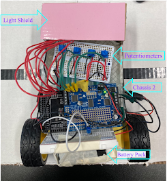
We found that the original chassis that we were given didn't have enough room for everything to fit, so we decided to create our own chassis that would be big enough to fit most things (especially batteries). We also decided to add walls around because small things like the 9V battery would easily slide down and if we decided not to tape something, it would still stay inside because of the walls.
Challenge 2:


We tested the motors using the provided code. The cart moved forward and then reverse. By adding some extra lines of code we were able to make the robot stop moving. We also temporarily attached all the circuits on the chassis. We are now in the process of soldering the circuit.


Explain what you have created, what functional modifications (need at least 2)
you made to the design and add a picture of your 3D printed chassis.
We wanted to have wall around the chassis so things wouldn't slide down. We also increased the area so we can fit more parts. We have two of the same chassis because the 3D printer cut off the top part for our first one so we had to reprint another one. However, we decided to use both of the chassis.


What is the purpose of the motor driver/shield?
It made it really easy to attach the motors and the batteries.


Challenge #7: Explain why you need to calibrate your photoresistor values.
What problem does this help solve and what problems do you still see coming from your photoresistors?
While the robot is in calibration, it reads the values from the photoresistors, which are between 0 and 1023. It takes these values and then maps them to either 0 or 100 (black or white). Calibration ensures that you have a uniformed measurement of white and black. If you fail to calibrate properly then the surrounding lights can alter the readings.
In the beginning we had trouble with the photoresistors. Some wires were touching each other, but even after fixing that one of the sensors still couldn't read. We solved that by fixing the positions and spacing the resistor legs farther.

What was the best PID values that you used? How well did this track? Any limitations?
The PID values changed as we moved from one map to other. For seeding round one, we kept the same PID values as given (P = 1, I = 1000, and D = 100), with speed being 60. However, we noticed that our robot went really slow and when we tried to increase the speed the robot was not able to follow the line smoothly. So for round two we decided to play with these values. We significantly increased the derivative value from 100 to 350. The robot followed the map very smoothly and did fifteen laps in one minute.
FINAL COMPETITION VALUES:
Frequency Sweep: speed = 60, P = 1, I = 1000, D = 75.
Circular Track: speed = 150, P = 1, I = 1000, D = 350.
Drag Race: final race speed = 185, P = 1, I = 1000, D = 370.
What does PID stand for? What is the purpose of the P, the I, and the D?
What steps did you take to choose the best values for your robot?
Explain this like you would for someone taking this course next year.
It was quite challenging to find the right PID values, but we were able to figure them out after testing many many times with different PID values. The key to find the right PID values was understanding how PID works and understanding how increasing or decreasing changes the output. By simply playing around with the PID values our robot was able to follow a lot of different lines.
PID (or Proportional Integral Derivative) is really helpful when you want a vehicle to follow a desired path. They are commonly used in autonomous vehicles. PID is a control system that uses error (how far away you are from the desired path) and manipulates it such that you get an error of 0. Increasing the P determines how much you turn towards a specific path. Integral tries to keep the steady state error to zero if it's not already at zero. Derivative resists the vehicle from moving too quickly towards a path. Choosing the right D value will ensure that our vehicle neither gets overdamped or underdamped when the path changes.
SEEDING ROUND #1
3 laps in 1 minute with speed at 60.
SEEDING ROUND #2
15 laps in 1 minute with speed at 150.
CIRCULAR TRACK
25 laps in 2 minutes with speed at 150.
FREQUENCY SWEEP
DRAG RACE
Different speeds for both the semifinal and final, 180 and 185 respectively.